During the terrible wildfires that we had in California in 2020, it was possible to know how good or bad the outside air quality was through PurpleAir’s excellent sensor network.
However, having all the windows closed due to the poor air quality outside, I was wondering about the air quality inside as well. While it’s definitely possible to get pre-made devices — such as PurpleAir’s indoor air quality sensor, IQAir’s indoor air quality sensor, or even something cheapo from AliExpress — building my own is much more interesting:
- It’s a fun project while being stuck at home during the pandemic
- It’s cheaper than a commercial unit, so I can put one upstairs and one downstairs
- It’s a good excuse to learn more about electronics
- With control over the firmware, it’s possible to do all kinds of things, such as logging the data over serial port or even sending the data over Wi-Fi to a
gen_tcpserver written in Elixir; once the data is on a more powerful computer, it can be logged to CSV to analyze in R, or one can make a fancy display with Phoenix’s LiveView - Did I mention it’s fun?
It’s also a pretty simple project; since all of the parts in the build have passive components included, the project is literally just buying parts, soldering them, putting the parts on a breadboard, and flashing the firmware. As such, a careful beginner could assemble this relatively easily.
Since it’s always a good idea to have an idea of what one is getting into before starting a project, the unit costs should be relatively low — less than USD$10 for just temperature and humidity to less than USD$70 for CO2, PM1.0/2.5/10.0 and tVOC depending on the cost of sensors — although getting the basic electronics tools required for this might add a bit to this. Time wise, this project can be completed in a few hours, with about an hour or two for each of the phases of this project — shopping, soldering, assembling, and installing the firmware — although one can tinker with the software for a while.
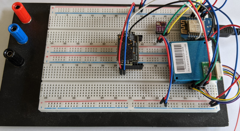
If you follow the instructions in this post, you’ll have this assembly on a breadboard, with data that can be read over the serial port or sent over Wi-Fi to a server of your own for further processing. It is powered through a USB port on your computer or any decent USB charger. This is what it looks like:
Since this is customizable, one could also opt for a very minimal version with a single sensor, such as this one.
And this is an example of a display that one can build (will be explained in a follow up post):
Since this is a learning project for me, I also started designing my first PCB for this, as well as an enclosure that can be 3D printed; in theory, the whole thing should fit within a pretty compact package.
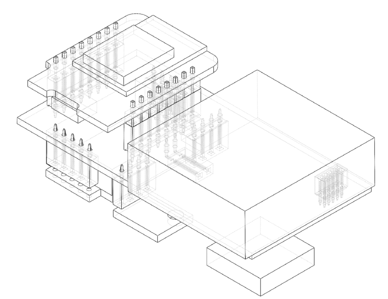
Neither the PCB nor the enclosure are finished, but once they’re ready and tested, I’ll post the files here.
The hardware
Air Gradient’s DIY sensor has a relatively similar BOM with an interesting combination of sensors. However, I wasn’t too much of a fan of their design; their build uses an older version of the Plantower particle sensor which is much larger, the CO2 sensor is soldered upside-down such that the CO2 permeable membrane faces the PCB instead of ambient air, all of the sensors are soldered directly to the PCB so that they can’t be reused/replaced, and their PCB seems a bit too large to place on a windowsill or other narrow location. I also didn’t care too much about the OLED display.
As such, this is the BOM that I have for this project, which is slightly different:
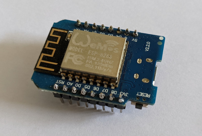
- WeMos D1 mini (ESP8266 board)
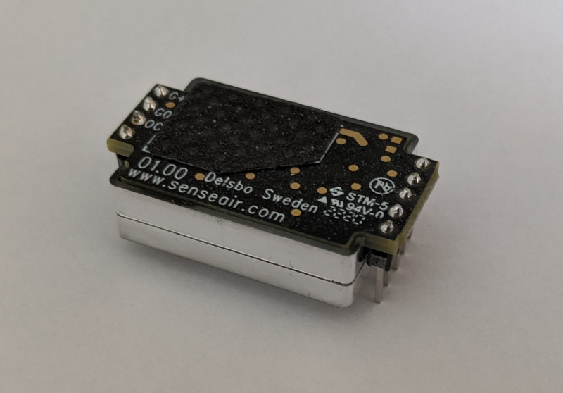
- SenseAir S8 CO2 sensor
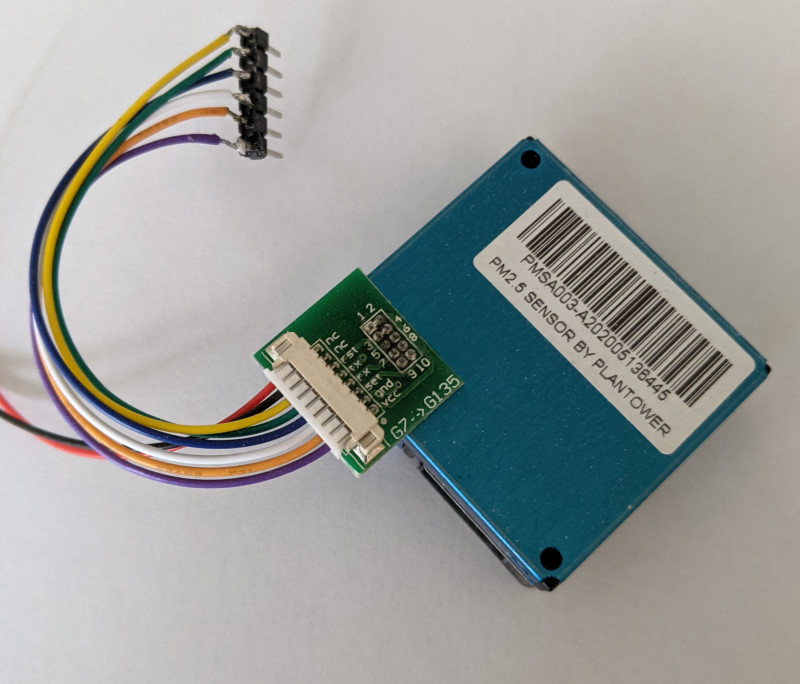
- Plantower PMSA003-A particle sensor
- SHT31 temperature and humidity sensor board
- SGP30 tVOC sensor
All of the hardware isn’t necessary, so if you don’t care about CO2 or particle counting, you can take that out of the build, it’ll still work.
Potential modifications
If you’re planning on just following the instructions in the rest of this post, you can skip this section.
It might be possible to use Particle’s Argon board instead of the WeMos D1 mini; I haven’t tried it, but it would have the advantage of having the charging hardware for LiPo batteries and integration with their IoT platform. They also have an air quality monitoring kit that has a different set of sensors, for the soldering averse.
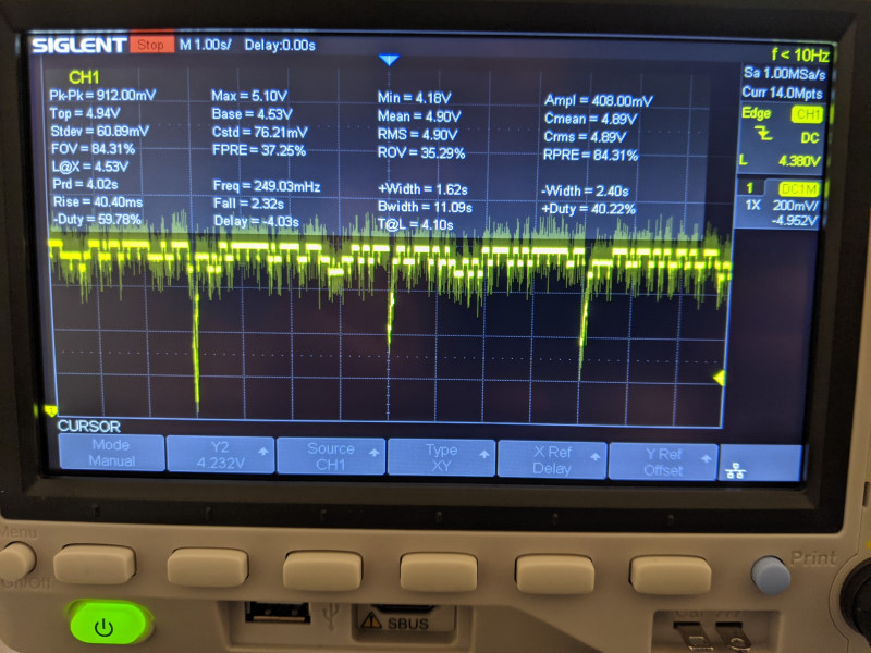
Another thing that I might change is replacing the SenseAir S8 CO2 sensor with a different CO2 sensor such as Sensirion’s SCD30; while the S8 works, the datasheet specifies that the average current usage is 30 mA with a peak of 300 mA, which seems to exceed the max 500mA at 5V that a USB port offers by default, leading to a bit of a voltage drop every few seconds. If the voltage drops too low, it seems that the SenseAir S8 returns erroneously high readings; if that’s the case, using a different USB power source and shorter USB cables may help.
Alternatively, since the SenseAir S8 CO2 is the most expensive part of this whole build, it could be replaced by the eCO2 approximation done by the SGP30. It won’t be as accurate, but depending on your use it might be “good enough.”
Shopping list
If like me you didn’t have anything that could be used to make electronics at home, here is a shopping list. These items can be bought from a local electronics distributor (eg. Mouser, DigiKey, AdaFruit, SparkFun, etc.) or AliExpress.
- The parts that you want for your sensor:
- WeMos D1 mini
- SenseAir S8 CO2 sensor (if you want a CO2 sensor)
- Plantower PMSA003-A particle sensor (if you want a sensor for PM1.0/2.5/10.0, good keywords for this on AliExpress are “PMSA003” or “Plantower dust sensor”) Other Plantower sensor models such as the PMS7003, PMS6003, PMS5003, PMS3003, and PMS1003 /should/ also work but will be larger. The letter after the model name refer to the orientation of the airflow in the sensor; if you’re not building a PCB and case, it doesn’t really matter which one you get. You’ll want to make sure that your sensor comes with a little rainbow colored cable, so that you can solder a connector to it as in this picture.
- If you want to avoid having to strip and solder wires, which is a bit finnicky, there is a breakout board that will give you male pin headers that’s available (search for “G7 adapter” on double lung electronic’s AliExpress shop).
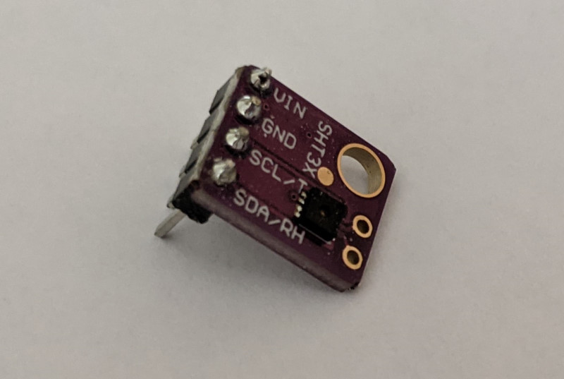
- SHT31 module (also referred as SHT3X, if you want a sensor for temperature and humidity, good keywords for this on AliExpress are “SHT30,” “SHT31,” should be a small purple board)
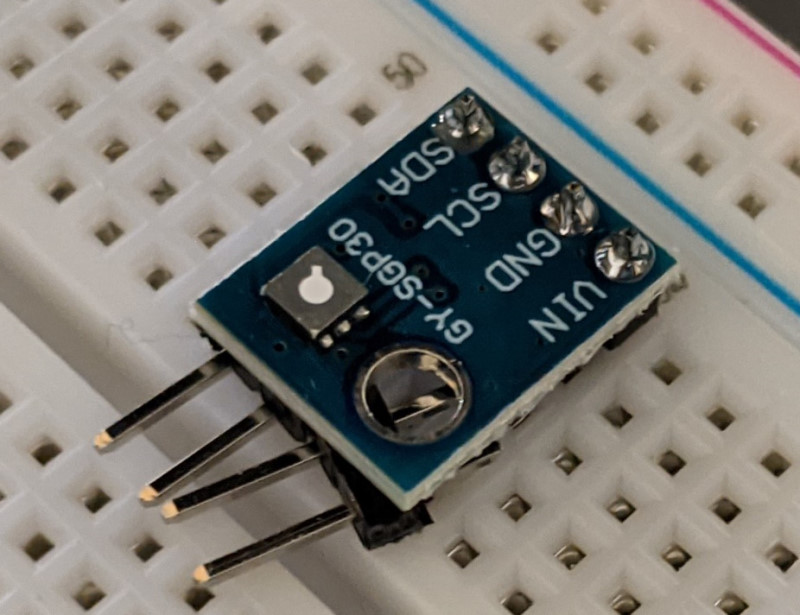
- SGP30 module (if you want tVOC sensing, and an approximate CO2 sensing, good keywords for this on AliExpress are “SGP30” and “GY-SGP,” should be a small blue board)
- WeMos D1 mini
- A micro USB cable
- A soldering iron: I got a Hakko FX888D but any soldering iron should do
- Some solder: I used Kester 24-6337-0018 leaded Sn63Pb37 rosin activated solder, but any leaded rosin solder should do. You probably want to get solder wire that is relatively thin to make it easier to solder these parts.
- A fume extractor; breathing solder fumes isn’t good for your health, I got the Aven 17701
- Some flux if you’re planning on soldering the wires from the particle sensor: I got a small bottle of Kester 959T flux from CMLsupply.com
- A few 2.54mm male pin headers
- Needle nose pliers to break off the male pin headers cleanly
- Small wire cutters to cut and strip the particle sensor wires
- A breadboard and jumper wires; I got a cheap one off AliExpress and regretted it, it had a short in it. Make sure it is wide enough if you’re using the SenseAir S8 CO2 sensor, as that sensor is too wide to fit on a single breadboard.
- A basic multimeter for continuity testing; if you have an oscilloscope or a logic analyzer handy, they might help with debugging if you encounter issues, but I wouldn’t buy them solely for this project
If you’re getting parts off AliExpress, arm yourself with some patience as it’ll take a while for everything to arrive.
Assembling everything
With all of the parts needed, what’s required is to solder the appropriate pin headers to the various module boards. For electronics beginners, you’ll want to search for how to solder electronics before starting to solder this.
If you’re not too sure about your soldering skills, solder the SHT31 module and the WeMos D1 mini first, as they’re the easiest parts to solder. You can then assemble the sensor to check that everything works, then come back to do the more expensive components.
Soldering
For the SHT31 module, you want to solder the pins such that the SHT31 sensor (the tiny chip with the little hole in the middle) faces up when placed on a breadboard.
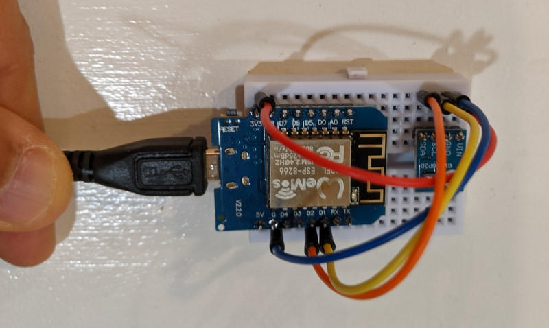
For the WeMos D1 mini, you want to solder the pins pointing below, as shown in this picture.
For the Plantower particle sensor, you’ll want to cut the rainbow cable in half, strip the wires, and solder some pins to the wires. You want to make sure to solder the VCC, GND, RX and TX wires. You can solder the RST and SET wires, but they’re not used in this build.
For the SenseAir S8 CO2 sensor, you’ll want to put the pins so that the pins stick out towards the body of the sensor. To do so, take some of the pin sockets from the WeMos D1 mini and place them on your breadboard. Break off two sections of pin headers (4 and 5 pins respectively), place them in the pin sockets, then place the S8 and solder away. The result should look like this.
Assembling
Now that you have the parts that you need soldered, you need to put them on a breadboard according to this schematic.
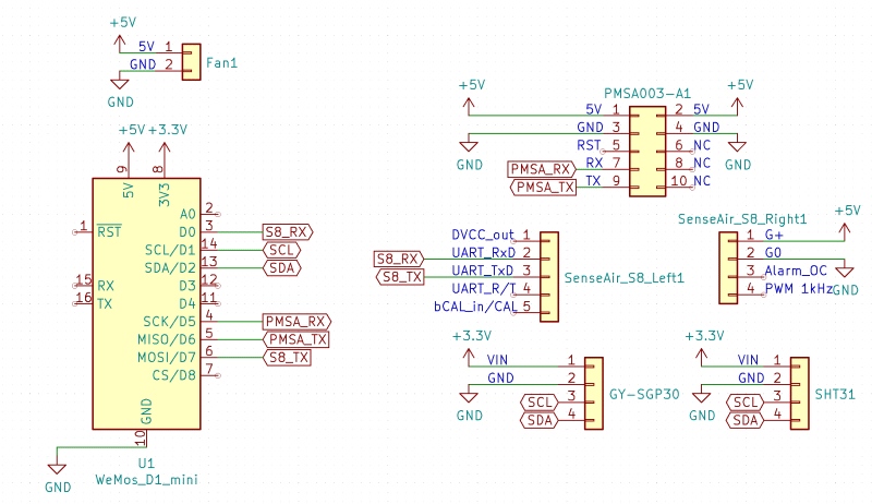
For the rest of us, this means that all of the 5V pins should be connected to the 5V pin on the WeMos D1 mini, all of the 3.3V pins should be connected to the 3.3V pin on the WeMos D1 mini, all of the grounds should be connected together, SCL and SDA should be connected to the SCL and SDA pins on the WeMos D1 mini, and the RX and TX pins from the other sensors should be connected to the pins indicated on the diagram.
For electronics beginners, you’ll want to search for how to use a breadboard before starting to assemble this on a breadboard.
In my case, I’ve used the left side of the breadboard for 3.3V and the right side of the breadboard for 5V; both grounds should be connected together.
If you’re using the CO2 sensor, you’ll want to put some pin sockets on the breadboard so that you can put the sensor in the pin sockets. The pins on the S8 are not very well labeled, so you’ll want to refer to the SenseAir S8 datasheet, page 3. With the PCB pointing away from the breadboard, the pins on the left from the top are G+, G0, OC, and PWM; on the right, starting from the top, they’re DVCC, RX, TX, RT, and CAL.
If you do it right, it should look like this:
To make sure that everything works right before plugging in the USB cable, use your multimeter on the continuity testing setting. For electronics beginners, you’ll want to search for multimeter continuity testing to learn how to do this. Make sure that all of the pins are connected as expected:
- All of the pins labeled GND/G0 should be connected to the G pin on the WeMos D1 mini
- The 5V pin should be connected to the G+ pin on the S8 and the VCC pin of the Plantower
- The 3V3 pin should be connected to the VIN pin of the SHT31 and SGP30
- The SCL and SDA pins should be connected to the D1 and D2 pins of the WeMos D1 mini, respectively (eg. SCL connected to D1, SDA connected to D2)
- The RX and TX pins of the particle sensor should be connected to the D5 and D6 pins of the WeMos D1 mini, respectively
- The RX and TX pins of the CO2 sensor should be connected to the D0 and D7 pins of the WeMos D1 mini, respectively
- There should not be any other connections than the ones listed above
The software
I’ve created a PlatformIO project and put it on GitHub. If you’re using the D1 mini, you can probably use it as is; I use the PlatformIO extension from VS Code. Make sure that you also have the CH340 driver installed from the WeMos site, as you’ll need it to flash the firmware using USB.
You can configure the project by editing the platformio.ini file, which tells PlatformIO which sensors to use and how to build and flash the firmware.
The first time that you flash the firmware, you’ll want to do it over USB, as the D1 mini isn’t running the software that would allow flashing it over the air yet. You’ll also want to have the ENABLE_SERIAL_DEBUGGING option enabled to make sure that you can get readings from the sensors.
Flash the firmware using PlatformIO and open the serial monitor; you should be seeing output similar to the one below. If everything looks good, then you can remove the serial debugging option.
Based on what you want to do, you can leave the air quality monitor attached to a computer and have it log data over the serial port; it’ll emit a single line every second or so that contains all of the sensor readings.
Alternatively, you can enable the network settings to have it connect to 2.4GHz Wi-Fi and send its data over a TCP socket. It’ll emit the same data as over the serial port, but it’ll do so over the network so that you can have multiple sensors that log data to a server. This also enables over the air flashing, so that you can update the firmware on the D1 mini without having to unplug it, plug it into a computer, then put it back into place.
If you want to go that route, the first time that you’ll boot the sensor, it’ll create an unsecured AP. Connecting to that AP shows a page that allows you to configure the Wi-Fi network to connect to, which will be remembered.
I have made a simple server in Elixir that will save the data every few minutes to a CSV file, and rotate the files such that there is one file per day. This should allow you to start playing with the sensor data in your favorite data science environment.
Conclusion
This was a pretty fun project! I still need to finish the PCB and case, but I’ve been running these air quality monitors for a few months now and it’s been pretty interesting to look at the data.
I’ll write a subsequent post that talks about the things I have learned about indoors air quality by monitoring the air quality at my place.
If you build your own air quality monitor, feel free to reach out; I’ll be happy to hear about how you built your own and what you’ve learned from it!